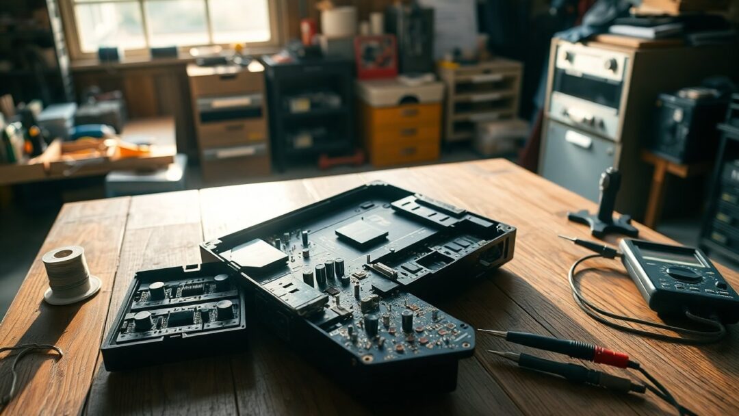
The story begins with a chance find: a partner spotted a vintage Philips Odyssey (the Brazilian-market version of the Magnavox Odyssey 2) at a pawn shop and brought it home as a potential restoration project. The unit looked rough, with many components visibly damaged, but it was valuable as a historic piece and an interesting challenge. Photos were taken before the system was dusted and cleaned, and the board is labeled MAIN BD 703965-5. The plan is to evaluate parts, replace what’s necessary, and try to bring the console back to life while preserving its originality whenever possible.
On the skills side: the primary technician is a beginner at electronics but comfortable with basic tasks such as soldering and desoldering large components and using a multimeter. The components on this board are relatively large, which makes manual replacement more approachable for someone still learning. There are at least a couple of known hardware revisions of these Brazilian consoles, so the exact layout can vary slightly. Additional photos can be taken upon request to help with component referencing or to clarify silk-screen markings.
Initial inspection and what to expect
After a first pass it’s clear many passive parts—especially electrolytic caps and some inductors—are badly deteriorated. Corrosion and physical bulging on capacitors are common in decades-old gear. Given the age, expect to replace several electrolytic capacitors and a few resistors that show heat damage or discoloration. The board marking MAIN BD 703965-5 is a key reference when cross-checking schematics or parts lists; if a schematic isn’t available, component values and board labels become critical. For safety, power up only after replacing suspicious mains-facing capacitors and verifying the power rail with a limit current bench supply or an incandescent bulb in series.
Parts identified
Capacitors and passive components
From photo inspection and initial AI-assisted identification, the likely capacitor set includes: one 4700µF 25V (marked C12 and noted as the main input filter), one 680µF 25V (C2207), one 47µF 25V (either C871 or C2208), three 10µF 50V caps (C782, C850, C853), and three 1µF 63V parts (C779, C783, C812). These are all common, large electrolytics or film caps and are usually available from local suppliers. Replacing electrolytics with equal or higher voltage ratings and similar or higher temperature ratings is standard practice to improve longevity.
Semiconductors and critical items
The semiconductor set identified consists of seven signal diodes, likely 1N4148 (spots labeled D701 through D704 and D685 to D687), one NPN transistor BC547 (Q684), and a voltage regulator 7805 for the logic supply. These parts are small but inexpensive and simple to replace. In addition to these, the listing flags critical items: resistor R7 (value to be confirmed by color code on the board), an oxidized inductor labeled L3 described as a bobina RF choke with a value of 12 µH, and a heavy-duty resistor of 33 Ohms 9W at R50 that is tied to the RF/video path and may affect picture output if faulty.
Next steps, sourcing and questions to ask
Most components were sourced locally except for the 12 µH inductor and the 33 Ohms 9W resistor, which can be harder to find in small electronics stores. If those specific parts are unavailable, consider equivalent parts with matching ratings and form factor; for the inductor, ensure similar inductance and current handling, and for the resistor choose the correct wattage and a low-inductance wirewound type if possible. Because AI-assisted identification was used but not fully trusted, it’s prudent to verify every component marking against the silkscreen and, when in doubt, post high-resolution photos of the board areas in question. Ask about testing strategies: performing continuity and diode checks with a multimeter, using an adjustable bench supply for power-up tests, and observing safety precautions when dealing with mains-connected parts. If the console powers but lacks RF output, focus on R50 and the RF choke L3 as likely culprits.
If you want feedback from the community, include clear, close-up photos of the damaged areas, the underside of the PCB, and any readable color codes or part labels. With the MAIN BD 703965-5 reference and the component list above, restoration becomes a step-by-step process: document, desolder, replace with like-for-like or improved specs, and test methodically. This is a valid and useful question for repair forums: it supplies the board ID, a component inventory, the technician’s skill level, and specific missing parts—precisely the details experienced restorers need to offer targeted advice and sourcing tips.


